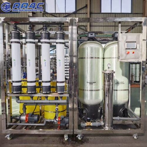
AA4C Automatic 4 steps Chemical Dosing System for Water Recycling for car washing machine Sewage treatment equipment
Preface
Thank you for using our company's HC-S type rotary blower. Before use, please read this manual thoroughly. Based on a full understanding, properly care for and operate the blower. Just like humans, the blower's
condition changes with various conditions every day; continuous
operation under different states can damage the blower. Regular
maintenance, inspection, and correct usage methods are crucial for
ensuring the blower operates smoothly and lasts longer.
Composition of the Rotary Blower
When air pressure between 0.1 kgf/cm² and 0.5 kgf/cm² is required, use
this blower. The blower consists of the following main components:
1.Motor
2.Air Filter
3.Blower Body
4.Air Chamber
5.Base (Oil Tank)
6.Oil Drain Valve
Introduction to Main Components
1.Blower Body
The blower body is the heart component that produces compressed air. This machine adopts the eccentric cylinder design developed by the
Japanese Toyo Company, which ensures high processing precision and
low operating noise.
2.Air Chamber
The air chamber stores compressed air from the blower body
continuously and reduces pulsation during discharge. It also serves as an
oil-air separator. The air chamber is equipped with a safety valve and
pressure gauge.
3. Air Filter
The air filter plays a crucial role in allowing clean air to enter the blower. Once dust or contaminants enter the main unit, they will wear down the
blower, contaminate the oil, and shorten the lifespan of the blower.
4. Drip Nozzle
The drip nozzle is a component designed to drip an appropriate amount of
lubricating oil into the main unit of the equipment. This model employs a
unique drop-by-drop structure innovated by Japan's Toyo Company, which is meticulously manufactured to prevent oil blockages and to
ensure that too much oil is not dripped into the system.
5. Base (Oil Reservoir)
The base of the blower serves as the lubricating oil reservoir. It utilizes
the pressure differential between the blower's intake and exhaust ports to
automatically and continuously press lubricating oil into the main unit of
the blower. The oil that is dripped into the main unit separates from the
air in the air chamber and then returns to the oil reservoir in the base.
6. Motor
The motor is not resistant to moisture; please ensure that it remains dry. Also, pay attention to the direction of rotation of the motor—it should be consistent with the directional markings indicated on the blower.
The working principle of the fan
When the eccentric device rotates the rotor in the cylinder body, the 4
blades in the rotor groove produce reciprocating motion, and the air is
sucked in, compressed and discharged to form a fan. Friction heat is
generated by friction between blade and rotor and cylinder block. Therefore, when the fan is running, the necessary lubricating oil is
dripped into the cylinder body by the drip nozzle to lubricate the friction
surface to reduce friction heat and friction noise; And a layer of oil film is
formed between the components to maintain the tightness of the fan. The
lubrication system is a circulation device that automatically supplies oil
by using the pressure difference generated when the fan works, so it can
not run with empty load!
Fan storage, installation, test operation precautions
(1) Storage
1. The best storage temperature of the fan is 15℃. If it cannot be met, it
also needs to be stored in a room without vibration and maintained at
room temperature. 2. The shell, frame and other components of the fan have been treated with
rust prevention at the factory, but the paint needs to be checked regularly
and repaired if necessary. To prevent internal parts from rusting, remove
the air filter and seal the air intake with a plastic film. 3.6
When the fan is not in use for a long time, it should be tested regularly. The hand plate is equipped with wheels once every half a month to ensure
that the blades are not too heavy and there is no stuck when rotating. Test
the edge performance of the motor every three months to ensure that the
resistance is more than one megaohm. 4. The fan has been lubricated before leaving the factory. If it is stored for a
long time, please replace or add lubricating oil before use to avoid
condensate or foreign matter in the oil in the body.
(2) Installation
1. Pay attention to safety when moving the fan to avoid damage and
impact on the fan. And the fan can not be carried upright to prevent the
lubricating oil from pouring out of the tank. Ventilation outlets should be provided in the air room and ventilation fans
should be installed. The ventilation outlets should be located in the upper
and lower places to facilitate air convection. 2. This prevents the fan from running normally due to the high temperature
in the equipment room. 3. It is best to have muffler materials around the inner wall of the
equipment room to reduce noise. 4. The fan is forbidden to be installed in the open air. In the case of
outdoor installation, a canopy should be put up to prevent rain from
entering. 5. The fan should be installed horizontally. 6. The diameter of the air distribution pipe should not be smaller than the
exhaust air diameter of the fan, and pay attention to the cleaning of the
pipe. The gas pipe should be installed above the water surface to prevent
the water in the pipe from causing excessive pressure when starting.7
7. Pay attention not to screw the check valve to (the protruding part of the
check valve should face up) when taking over. 8. Please connect the wire correctly and note that the motor steering is
consistent with the fan rotation direction mark. 9. When two fans are operated alternately, it is hoped that frequent
switching of the fan should be avoided in a short period of time
The continuous operation time of the fan is not less than 24 hours.
(3) Trial operation
1. Check whether the oil in the tank is up to standard. (Engraved line
marks on the oil scale)
2. Before starting the fan, please take down the air inlet filter and pour
about 30m1 oil into the main engine so that the oil is evenly distributed
inside the main engine. (Turn a few times with your hand)
3. Check whether the tightness of V-belt is suitable, if it is too loose, please adjust. 4. Check whether the safety valve is set at the specified pressure position. If the working pressure is 0.3kgf/cm, the opening pressure of the safety
valve is 0.33kgf/cm. In the test run, you can manually adjust the exhaust
valve boost pressure to open pressure, adjust the safety valve to open, adjust the safety valve to open. (The pressure is 1.1 times the working
pressure)
5.Turn on the power to start the fan, please pay attention to the following;
a. Whether the direction of the fan steering is consistent with the direction
indicated by the steering mark, if not consistent, immediately stop and
adjust the motor wiring. b. Check whether the pressure gauge indicates pressure. (The sewage
treatment tank must be filled with water before running the fan, otherwise
there is no pressure at the fan exhaust port, the fan is not lubricated.)
c. Observe whether there is oil dripping out of the drip nozzle (12-158
drops/minute), and observe whether there is oil flow in the transparent
return pipe. d. Check whether all parts of the motor and phoenix are running normally, whether the temperature is normal, and whether there is abnormal sound. Fan maintenance points
1. Check the lubrication system
a. Daily check whether the amount of oil stored in the tank is lower than
the minimum scale line, if the oil is insufficient, please refuel. (The oil
brand is IS0 standard N68 anti-hydraulic oil, and the oil brand can be
appropriately reduced in low temperature and cold areas)
b. Daily check whether the oil is mixed with water and other dirt and
deterioration, such as deterioration, please replace the hydraulic oil in
time, under normal circumstances, replace the hydraulic oil at least once a
year. c. Clean the oil filter daily. d. Daily check whether the dripping condition of the drip nozzle is
normal. If the drip nozzle is dirty, remove the adjusting screw to clear it
For washing. 2. Inspection of air filter
Daily check whether the air filter is dirty. If dirty, remove the air filter, unscrew the butterfly nut, remove the cover, and clean the filter sponge. (Be careful not to drop stolen goods into the fan host when unloading the
filter)
3. Inspection of triangle belt
After the fan runs for a period of time, the triangular belt will stretch. At
this time, the fixing bolt of the motor should be loosened, the motor9
should be moved, the triangle should be tightened to the appropriate
position, and the motor fixing bolt should be tightened, and the end
surface of the motor pulley and the fan pulley should be on the same
plane. At the same time, check whether the top tightening screw of the
pulley has been sent off. If it is loose, please hold it tightly. 4. Check the flexible condition of the safety valve on a daily basis. If it is
not flexible, please clean and debug it to ensure reliable opening and
closing. 5. Check and repair the parts for oil and gas leaks on a daily basis. If it
cannot be repaired, please inform the manufacturer immediately. 6. Clean up the fan factory every day, keep it clean and well ventilated. 7. Check the operation status of the fan and motor frequently. If you find
that the noise and temperature are not normal, you should stop and repair
it in time. The cause of the fault and the handling method are shown in
Schedule I and Schedule II. Fan repair method
In case of fan failure, please check carefully, determine the cause of the
failure, and then repair the parts that need to be replaced according to the
parts list. 1. The dismantling of the fan host
a. Remove the belt cover and belt
b. Loosen the fastening bolts on the end cover with the TOHIN mark on
the side. c. Screw bolts into the two threaded holes on the end cover and remove
the end cover. d. Remove the V-shaped pulley from the shaft.10
e. Loosen the bolts securing the end cover on one side of the V-shaped
belt pulley and remove the end cover. Note: When disassembling the main machine, be careful not to hurt the
parts, and the removed parts should be carefully placed. 2. Fan main engine repair
After disassembling the main machine, polish the rotor, cylinder block, end cover, blades, rings and other parts with fine sandpaper or oil stone. Clean it carefully with cleaning oil or gasoline (be careful not to hurt
parts) and then reassemble it. The initial burn damage mixed with debris, water and other faults, can be repaired by the above methods, bearings, oil seals and other damage, need to be replaced. Also be sure to replace
the 0 ring. 3. Assembly essentials of fan host
a. Place the end cover with shaft holes on the assembly table. b. Place the pulley of the rotor shaft side down on the end cover. c. Insert the spring top pin into the rotor shaft (above HC-60S). d. Insert the blade into the rotor slot. e. Put the cylinder block (note that the position of the air outlet is on the
side of the rotor next to the hole in the cylinder body)
f. Put in the branch ring (HC-501S below). g. Install bearings. h. Install O-rings. i. Install the other end cover and secure the bolt. j. Turn the cylinder block over and remove the end cover on this side of
the pulley
k. Put the branch ring (less than HC-501S). l. Install bearing and 0 ring. m. Install an oil seal on the end cover. n. Install the end cover, fasten the positioning pins, and tighten all bolts.11
o. Stand up the main engine, fasten the positioning pin of the end cover
on the other side, and tighten all bolts. p. Pour a small amount of lubricating oil into the air inlet, fix the pulley
on the rotating shaft, and rotate the pulley O by hand. At the same time, use a wooden or rubber hammer to gently tap the reinforcement of the
end cap to make the rotor rotate flexibly. Fan outline, installation size drawing
phenomenon reason measure
High noise 1. Pipe blockage causes pressure
rise
2. Improper installation of belt
cover causes vibration
3, motor bearing wear
4, dust into the fan caused by
grinding
5, no lubricating oil
6, poor lubrication
7. V-shaped belt wheel is loose
8. Triangle belt slip
1. Clean or replace the pipeline
2. Reinstall the belt cover
3, replace the new bearing
4. Disassemble and repair the
fan
5. Check the oil supply system
6, clean the drip nozzle and oil
filter
7. Tighten the top wire
8, adjust the belt tension12
fever 1, overload operation
2. The fan inlet filter is blocked
3. Fan rotor is biased
4. Cut off lubricating oil
5. Belt slip
6, poor lubrication
7, the fan internal damage
1. Check whether the pipeline is
blocked
2, clean the air filter
3. Gently tap the end cover with
a wooden hammer
4. Replenish oil and check oil
supply system
5, adjust the belt tension
6. Change the oil and clean the
drip nozzle and oil filter
7. Disassemble and check the
fan
Insufficient air
volume
1. The fan inlet filter is blocked
2. No lubricating oil
3, poor lubrication
4. Belt slip
5, pipeline air leakage
6. The pipe is too long
1. Clean the inlet filter
2, check the oil supply system
and the amount of oil
3, clean the drip nozzle and oil
filter
4, adjust the belt tension
5. Fix the pipes
6. Reset the pipeline
Fast fuel
consumption
1, overload operation
2, the air filter is blocked
3. Oil leakage
4, the temperature is too high to
cause oil evaporation splash
1. Check the pipeline system
2, clean the air filter
3. Fix it
4. Check the cause and fix it
Belt breakage 1. Overload operation
2. Belt slip
3. The two belts are not parallel
1.adjust
2.adjust
3.adjust
Motor stall 1. Overload
2, fan abrasion
3, the power cable is poor
4. The internal motor is too dirty
or the bearing is damaged
5, the motor itself has quality
problems
1. Check the pipeline system
2. Maintenance
3. Repair
4, clean the motor or replace the
bearing
5. Replace the motor13
Schedule II Fault tree
The air filter is blocked
overloading Exhaust line clogging
Transport collision rotor deviation
Motor Poor insulation
failure Electric machine Too dusty
flooding
Bearing failure
Bad wiring interrupts the line
The fuse blew No lubricating oil scratch
Bad fan Mixed with dust and other dirt
Voltage too low Water rust
Overheat trip Rotor deviation, bearing damage
Run under no load
Oil leakage
Oil filter connector screen is blocked
No lubricating oil scratch Pipe failure
The air filter is blocked
There is not enough fuel in the tank14
High noise The belt cover is unstable
The foundation base is improperly installed
The sound attenuation design of the equipment room is poor
Compression sound caused by excessive pressure
The bearing of the motor or fan is damaged
Motor The rotor of the motor collides with the stator
rotation Bad fan The drip nozzle is blocked
Oil filter clogging
Lubricating oil deterioration
Bearing failure
The fan internal parts are damaged
Insufficient lubricating oil
Insufficient Poor oil quality
exhaust Air leakage in oil passage
Inlet filter clogging
The belt slipped loose
Aging of oil seal
Oil leakage Bad seal ring
Bad joint
Air leak in the air chamber15
Poor lubrication
Fan abrasion
Abnormal temperature The installation valve failure pressure is too high
Air filter clogging
The fan rotor is biased
The space of the air room is too small and the
ventilation is poor
The motor is rotating in the wrong direction
Repair and warranty
If the fan fails, please inform our company. Regarding the repair and
warranty of the fan, please deal with it as follows. 1. The warranty period of this product is within one year from the
date of delivery. 2. During the warranty period and under normal operation, the
failure and damage caused by poor product design shall be repaired free
of charge, that is, our company shall bear the cost of repairing parts and
the travel expenses of the staff sent, and other expenses shall not be
borne.3.Charge for repairs to the following faults:16
(1) Failure damage after the warranty period;
(2) Equipment failure and damage caused by improper use or
storage;
(3) Fire, flood, natural disaster, earthquake and other disasters and
irresistible failure and damage;
(4) Failure and damage caused by the use of parts other than those
specified by our company;
(5) Accident, failure or damage caused by repair and renovation in a
maintenance department other than that designated by our company;
(6) Accidents, failures or damage caused by use other than
performance parameters and misappropriation for other purposes
Bad;
(7) Accidents, obstacles or damage caused by foreign bodies such as
corrosion, dissolution, adhesion and mixed solids due to solvent drugs;
(8) Accidents and failures caused by natural block of valves, overload, etc. :
(9) Accidents caused by corrosion and rust. 4. Do not compensate for the various costs and other losses caused
by this product in the process of use, and consider the accident, it is best
to choose a spare fan.17
Warn : Personnel other than full-time maintenance operators are
strictly prohibited to participate in the repair, incomplete repair will cause
electric shock, fire and other dangers. This manual is used on behalf of others. Please contact us if you
have any questions.
Related Products
AA4C Automatic 4 steps water recycling system for car washing machine Sewage treatment equipment